Introduction
A site-to-site connection between two venues is one of the key USPs of the Stream Conversion Gateway, this guide explains how to do this using 2 Stream Conversion Gateways running firmware v1.3.0 (and later) and using the IPMX SRT transmission method.
Pre-requisites
Setting up a site-to-site connection has a few pre-requisites:
- A high bandwidth, non-blocking VPN tunnel, like wireguard, between two venues, or
- At least one of the two Stream Conversion Gateways to be exposed to the internet using port forwarding.
- A source and destination at each venue to validate.
For this guide we’ll be using a 19” Stream Conversion Gateway Advanced frame.
Step 1 – Port forwarding and SRT modes
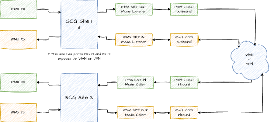
SRT is a unicast protocol that will generally easily travel over WAN connectivity, but it does need inbound and outbound ports to be opened, for the sake of this guide we’ll use the 10000-10010 range of ports. With how the IPMX SRT setup is currently integrated in the Stream Conversion Gateways we cannot use streamids to differentiate multiple connections on the same port, so for each outbound stream we’ll use a new port.
These ports need to be opened on the SRT “Listener” side, to learn more about SRT modes, check out this link: https://doc.haivision.com/SRT/1.5.3/Haivision/srt-connection-modes
The listener should have bidirectional ports opened, the caller only needs to have outbound opened.
It’s typically recommended to utilize a VPN tunnel like Wireguard to setup a secure connection between the two sites
If you look at Figure 1, you can see how we’re setting it up, note that “Caller” and “Listener” don’t equate directly to sender/receiver, it’s a tunnel initialization, not a traditional “RX/TX” relationship.
Step 2: Setting up a route to transmit IPMX
Navigate to the webUI of SCG Site 1, create a new route, select your IPMX as Source and create a new Destination

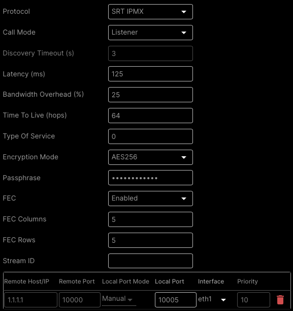
Properties for creating a SRT IPMX Destination
Call Mode
Now let’s edit the SRT IPMX Destination 1 route, first we’ll update the “Call mode” variable to “Listener”.
Latency
After that we’ll update the latency, to set a latency, initialize a ping from the network of SCG Site 2 to SCG Site 1, note down the roundtrip time, e.g., 124ms, and quadruple that to get a best practice latency.
So, if my roundtrip between Site 1 and Site 2 is 124ms, we calculate the latency like so: RoundtripMS x 4 = latency.
This is a best practice and could be tuned downwards if desired, albeit that could cause jittering/stuttering of the signal.
Please note that latency should be configured identical on both sites, this value needs to match exactly.
Bandwidth overhead
To allow for bursting behavior, typically seen in h264/h265 datastreams we need to add some allowance for bandwidth overhead, we recommend 25%, note that this will be added on top of the bitrate for the AVN High Compression stream.
Time To Live – Hops
It’s possible to restrict how many hops the signal is allowed to take, typically you don’t need to change this unless you’re doing some advanced signal routing, for the sake of this guide we’re keeping it at 64.
Type of Service
You’re also able to add a Type of Service header decimal for integration with QoS in routers, for the sake of this guide we’re keeping it at 0.
Encryption
As we’re most likely traversing WAN, it’s recommended to enable encryption, let’s select the heaviest at AES256 and type in a secret key, please note that this should at least be 10 characters.
 FEC
FEC
Forward Error Correction, or FEC for short, is not part of the SRT specification, but integrated in the SCG pipelines to efficiently handle bitrate spikes and highly dynamic content. Especially when traversing WAN we recommend enabling FEC, depending on experienced artefacting the amount of columns/rows can be tuned.
StreamID
We’re leaving the StreamID empty at this moment.
Connection details
The connection details are relatively straight forward on the listener side, we set the local port, in our case 10000, and select the interface that is WAN facing (e.g., eth1).
After we’ve set all these, press “update”.
Step 3: Setting up a route to receive SRT IPMX
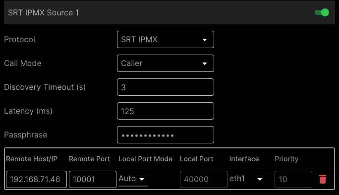
Similarly to how we’ve setup a transmitting route for converting local IPMX to SRT IPMX, on the SCG Site 2 we’ll have to pick that signal up and convert it back to SRT, we do that by creating a new route and adding an SRT IPMX Source as input.

Properties for creating a SRT IPMX Source
Call Mode
We’re going to be using the Call Mode “Caller”, matching our “Listener” mode at SCG Site 1.
Discovery Timeout
This setting allows for tweaking longer handshake requirements, especially using VPNs or large roundtrips this might be required to be tweaked, for now we’re leaving this at 3 seconds.
Latency
We should match the latency settings of the SCG Site 1 output.
So, if the roundtrip between Site 1 and Site 2 is 124ms, we calculate the latency like so: RoundtripMS x 4 = latency.
Passphrase
As we’ve setup using encryption on the transmitter side, we need to provide the Passphrase we’ve setup there as well.
Connection details
A bit different from the transmitter side here is the Connection details.
Remote Host/IP
Fill in the IP that we can reach the SCG Site 1 at, this could be your router’s public IP with the port forward, or an egress IP through the VPN tunnel.
Remote Port
Similarly to us requiring to provide the public IP of SCG Site 1 we need to provide the “Local Port”-value of the Listener SCG here. If we have set that to port 10000 we should also have 10000 in the Remote Port on SCG Site 2.
Interface
Select the WAN/VPN facing interface here, e.g., eth1.
After this press update and you should start seeing bitrate on the route.
Step 4: Validate AVN-4/2 Encoder settings
To make IPMX SRT smoothly work over non-IPMX optimized connections, like a WAN or VPN connection we have to validate some settings on the encoder side of things.
Please note that the Stream Conversion Gateway only interacts with High Compression (H.265, H.264) streams.
Bandwidth considerations
Before proceeding with settings, consider what signals you want to transfer, how many and what your available bandwidth is at both sites. This will determine whether it’s realistic to go 4K native, or scale down to 1080p, as well as the level of compression you might want to apply.
Scaling
If we decide to scale between two locations, navigate to the Scaler Setting panel in the AVN and press the Edit button.
The output scaler is shared between the Light and High Compression streams, but you’re able to enable or disable it independently between the two.
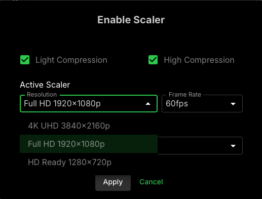
If you’re restricted in bandwidth, it might be worth considering to scaling to 1080p or even 720p in highly constrained environments or if visual fidelity doesn’t matter much with the content transmitted.
Encoding settings
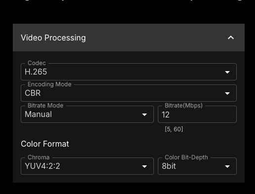
Now more importantly, let’s evaluate the High Compression Stream encoding settings. Navigate to the High Compression Stream(H.26x) panel and press the Edit button next to Video Output.
In this screen you want to ensure the following settings:
Codec
H.265 for most optimal compression (but H.264 is fine as well, if you need that for compatibility reasons).
Encoding Mode
CBR instead of VBR, to stabilize bitrates
Bitrate Mode
Manual, with a recommended minimal bitrate of 8Mbps at 1080p60 and 24Mbps at 4K60 using H.265
Decoding settings
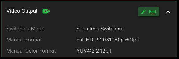
Decoding SRT IPMX signals is handled by the receiving AVN decoding unit, for the best experience, navigate to the “Video Output” widget and click “Edit”
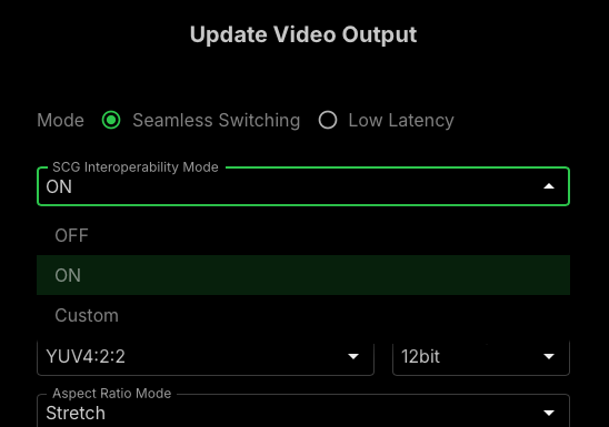 SCG Interoperability Mode
In the Video Output Configuration modal, we’ll set the SCG Interoperability Mode to “On”, this adds about 1 frame of latency but will make for a smoother decoding experience where network stutters have less risk to cause visual distortion.
If you’re encountering issues with 3rd party encoders it might be worth considering setting this value to Custom and tune your buffer manually.
Was this article helpful?
That’s Great!
Thank you for your feedback
Sorry! We couldn't be helpful
Thank you for your feedback
Feedback sent
We appreciate your effort and will try to fix the article